Diagram Of Oil Well
Co2 enhanced oil recovery explained – melzer consulting Casing wellbore deepwater Oil drilling wells gas diagram well injection diagrams rig co2 flood rigs geothermal procedures generators pump recycling electricity driller rock
CO2 Enhanced Oil Recovery Explained – MELZER CONSULTING
Fracking diagram fracturing hydraulic oil well graphic shale explained gas great frack natural earthquakes method basics reuters water made geographic Well oil surface production subsurface wellhead equipments gas components equipment component completion functions introduction domain accessories drilling which provides structural Oil well drilling: explained
Reservoir conventional adapted scirp
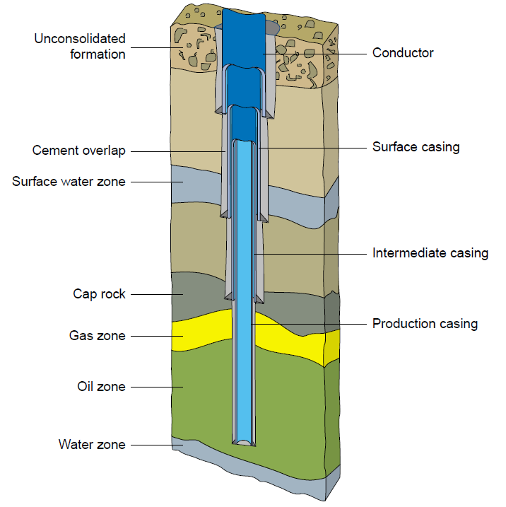
Wellbore casing drilling well pipe fluid oil gas production hole cement cased engineering wellhead terms stability which figure drilled itsA—schematic of well casing program Petroleum valuethemarkets basicsWell casing tubing gas production schematic vertical oil completion wellbore flow cased typical perforated wells casings petroleum surface natural liquid.
Oil creation and production:what you need to knowCasing program and wellbore heat transfer of typical deepwater wells Well completion schematic for well#01 (horizontal).Methods in oil recovery processes and reservoir simulation.

Oil well
Table applications of api cementsSagd co2 completion enhanced heavy pumping crude considerations Oil wellOil well pump jack diagram petroleum energy figure.
6.2: introduction to gas and liquid flow through well tubingOil well fracking diagram Cement cements applications lb engineeringOil drilling procedures.

Drilling rig circulation petroleum britannica oilfield fluids crude fluid bore rigs geothermal bentonite based borehole wellbore infographics schematics flowing jasa
Completion schematicOil drilling rig petroleum oilfield well works conventional gas derrick rigs engineering drill diagram fracking vs systems work energy components Drilling and casing the wellboreBetter models for better oil well control.
Well completion .


Casing program and wellbore heat transfer of typical deepwater wells

6.2: Introduction to Gas and Liquid Flow through Well Tubing | PNG 301

Table Applications of API Cements - Drilling Engineering - Rig Worker

Better Models for Better Oil Well Control

CO2 Enhanced Oil Recovery Explained – MELZER CONSULTING

a—Schematic of well casing program | Download Scientific Diagram

Oil well - Energy Education
Drilling and Casing the Wellbore - IndustriMigas | #1 Oil and Gas Blog

Well Completion Schematic for Well#01 (Horizontal). | Download