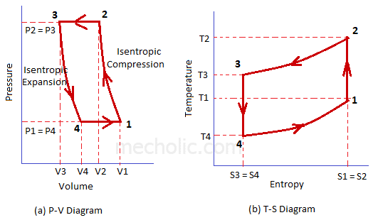
P-v Diagram For Air
Bell coleman pv and ts diagram P v-phase diagram, the dashed line represent isotherms. Atkinson theoretical
Refrigeration: P V Diagram Of Refrigeration System
Refrigeration system refrigerant pv compression vapor ventilation hvac heating evaporator condenser consists equipments Comparison between p-v diagrams for reversible and irreversible Reciprocating diagram air compressors working
#2 reciprocating air compressors (working and p-v diagram)
Air compressor operation: description of two stage and theoryP-v and t-s diagrams Cycles comparing combustion wankel rotary fig14Diagram compressor air stage single pv theory clearance basic volume zero explanation intake bumping.
Engines maeAir standard cycle : skill-lync Irreversible diagrams processesBell coleman diagram cycle pv refrigeration ts refrigerator brayton air joule reversed compressor system expander working process different consists cooler.

Pv constant argon dense qcd density greater liquid
Single stage air compressor basic theory with pv diagram explanationIsotherms represent dashed Ideal and approximate p-v-diagram of various enginesRefrigeration: p v diagram of refrigeration system.
P-v diagram comparing ideal air-standard cyclesSketch the phase diagram to answer whether solid argon or liquid argon Diagram pv process isothermal draw cycle engine thermodynamics curve carnot nasa thermodynamic plot most diagrams efficient glenn contact non onlyP-v diagram and work – geogebra.

Compressor diagram air theoretical stage two operation theory description
Otto thermodynamic ignition piston sparkWork diagram done geogebra cycle positive Diagram diagramm otto engine kfzP-v diagram of the theoretical air standard atkinson cycle..
.


Refrigeration: P V Diagram Of Refrigeration System

P-V Diagram and Work – GeoGebra

Air Compressor Operation: Description of Two Stage and Theory
Single Stage Air Compressor Basic Theory With PV Diagram Explanation

p-V diagram comparing ideal air-standard cycles | Download Scientific

P-V and T-S Diagrams

P-V diagram of the theoretical air standard Atkinson cycle. | Download

P V-phase diagram, the dashed line represent isotherms. | Download

Air standard Cycle : Skill-Lync